
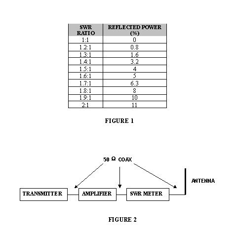
Standing wave ratio (SWR) is a method of evaluating impedance match between a generator and a load. Standing wave reflections on a transmission line are undesirable and reduce the generators ability to transfer power to a load. The closer the SWR ratio is to 1:1, the fewer the reflections giving more efficient power transfer. It should be noted that attaining a 1:1 (ideal) match is impractical given real-world conditions. Figure 1 shows various SWR ratios and the associated percentage of reflected (wasted) power.
How will SWR affect my amplifier and system?
Per the definition above, the amplifier can be thought of as the generator, while the antenna system can be thought of as the load. Impedance matching between the amplifier and the antenna is critical to the longevity of the amplifier as well as overall amplifier performance. An improper impedance match (high SWR) will cause the amplifier to run much hotter and will reduce available output power. This condition can also lead to premature amplifier failure due to excessive heating. Impedance matching in these types of communication systems is normally accomplished at the antenna. With the use of an SWR meter and appropriate length adjustments of the antenna radiator, a satisfactory match between amplifier and antenna can be achieved. This assures the coolest possible amplifier temperatures and maximum power transfer from amplifier to antenna.
What SWR ratio is acceptable?
Obviously, the lower the SWR ratio the better your system will perform. Practically, it's not possible to achieve a 1:1 matching condition. As a rule, amplifiers up to the 500W range should not exceed an SWR of 1.8:1. This will ensure that heat dissipated within the amplifier caused from mismatch reflections is within tolerable limits.
What is the procedure for setting SWR?
As stated earlier, the SWR ratio is normally reduced by changing the length of the antenna radiator. Follow the steps below for proper adjustment:
IMPORTANT - MOST SWR METERS ARE NOT DESIGNED TO HANDLE HIGH POWER LEVELS,MAKE CERTAIN AMPLIFIER IS OFF FOR ALL SWR MEASUREMENTS AND ADJUSTMENTS
· Insert an SWR meter in the system as shown in figure 2.
· Key the transmitter and note the SWR ratio reading. (Refer to the SWR meter instruction manual for exact measurement procedure for your particular model meter.)
· If ratio is greater than 1.8:1 adjust the length of the antenna radiator and recheck. Repeat measurement/adjustment procedure as necessary until ratio is 1.8:1 or less.
· Remove the SWR meter from the system and reconnect antenna to amplifier output.
· This concludes the adjustment procedure; the amplifier is ready for operation.
