

"Proper Station Grounding and Avoiding Ground Loops"
PROPER STATION GROUNDING AND AVOIDING GROUND LOOPS
We all have read quite a bit of posts where many well-meaning comments and suggestions about "grounding" and "bonding" are made. There are many in the world and on this Forum who......simply don't ground at all, some ground with for instance a 10AWG wire, others use a couple of straps, and still others yet "ground ground ground" everything in sight. Even with the latter, it's not just how much you ground, but additionally and actually how and where you ground. It has to be methodical and done in an organized fashion, with a few key rules practiced.
One thing that only occasionally (actually rarely) is mentioned are the formation of ground loops as a result of improper grounding methods. Or how to avoid them. I've tried to do car audio & CB installs both in such a way to avoid (or minimize) the chances for them to occur. This after prior negative results.
This is a very common plague in mobile car audio systems combined with car audio amplifier installations, as well as for transmitting radios like CB & Ham radios. My first experiences with ground loop problems were many years ago doing the car audio installations. A great source of electrical system noise was introduced into the stereo & amp sound system via improper grounding. The car was very "well grounded", but improperly.
Ground loops will not always show up as "electrical noise", indicating and tipping you off to it's presence. There may be "RF hot" wires, mic's and radiating coax----aka "RF in the shack" as it's commonly called. Additionally resulting also in TVI interference and bleeding. By grounding correctly, this will also increase the safety factor of your installations, in the event of a surge or lightning strike.
Ground Loops
GROUND LOOPS
Defined, a ground loop is: "In an electrical system, a ground loop usually refers to a current, generally unwanted, in a conductor connecting two points that are supposed to be at the same potential, often ground, but are actually at different potentials. Ground loops created by improperly designed or improperly installed equipment are a major cause of noise and interference in radio, audio and video systems. They can also create a hazard, since ostensibly "grounded" parts of the equipment, which are often accessible to users, are not at ground potential."
So a ground loop is formed when station equipment, both fixed & mobile----are at two or more different "ground potentials". Every piece in the "radio system" should share a single common ground potential. A "common grounding point" to share the same potential, if at all possible. Sometimes referred to as a "star ground" or using the "star ground method". This should be for DC and RF grounding alike, when at all possible. "Random" ground placements essentially all over or at the nearest convenient spot can introduce more problems than they could cure. On one hand, it's always advised to keep a ground strap as short as possible. That's true. But not at the expense of an improper grounding site selection, by choosing a poor location to affix the bonding connection.
As said, avoid linking and your grounds in such a manner as pictured in the first diagram below. This is commonly referred to as "daisy chaining" and, although it can appear neat & orderly---it is a definite no-no and maximizes the chances of introducing unwanted noise into your radio audio system.
Improper Station Setup Introducing/Producing Unwanted Ground Loops
[ external image ]
In the second diagram pictured here, the popularly dubbed "star method" or "single point grounding" of attaching and affixing your equipment grounds at one place only is illustrated. Every piece of station equipment shares the SAME single common reference point for single station ground. These two examples above and below, of what to do and what to try and avoid----hold true in fixed base station installs and mobile installations alike. The use of coax line isolators is further utilized in this example to heighten effectiveness. Although I don't own any line isolators yet, I certainly plan on adding them to my home station when I'm finally established with a more permanent setup.
Proper Station Setup Reducing/Eliminating Unwanted Ground Loops
[ external image ]
The information here is fairly decent and should (at the very least I hope) be thought-provoking. Another good area possibly to improve your overall station setup, installation and system performance. Certainly, a very worthwhile effort.
Here is an excellent reference specifically for mobile ground loops, my favorite KOBG of course! (go to/click on:---ground loops)
[Please login or register to view this link]
Hope this helps all and
Happy Dx'ing!
Foxhunter 351 NJ '09
Proper Station Grounding and Avoiding Ground Loops
-
Foxhunter

- Donor

- Posts: 2,651
- Joined: April 3rd, 2008, 11:24 am
- Radio: Fisher-Price
- Contact:
-
North Texas Mudduck
- Wordwide & Qualified

- Posts: 2,921
- Joined: September 30th, 2006, 8:22 pm
- Contact:

-
Foxhunter
- Donor
- Posts: 2,651
- Joined: April 3rd, 2008, 11:24 am
- Radio: Fisher-Price
- Contact:
The radio station gear in Fig. 2 are (in effect) series-connected and "daisy chained" together via the coax shield, the DC power cable which is something to be avoided if at all possible. This forms "loops" which act as a loop antenna and are good at picking up or delivering unwanted signals.
The radio station gear in Fig. 5 each, individually and separately, go to and meet at one common ground point, often a main ground plate. The plate is connected to a ground rod just outside.
The "other" ground shared by the coax shield is present in both diagrams, but in the 2nd example, in addition to using single-point grounding, it has also has the additional benefit the coax line isolators between each unit. Some will use snap on ferrites. Still, even without the isolators, the ground wiring is correct.
Aside from using the proper single point grounding method, these "isolators" are a great way to go. They are also used in audio applications for the very same reason (called ground loop isolators). Isolators are also used in video system installations, and also in computer system installations. Ground loops cause problems in audio/video, computer and in RF transmitting radio systems. Common proper grounding is the key starting point in the installation, and isolators seem to be a second beneficial component(s).
Common point grounding is commonly referred to as "star system grounding". Simply put, star grounding means that you designate some special terminal as the "star ground" for the system. All other "grounds" will be referred to this one single point. Then every single unit that is connected to ground in the whole system has its own separate wire run to the main star ground point. The ground wires radiate away from the star ground in all directions to the individual system units, hence the name "star".
Too many improper grounds in a system could create a big ground loop, which could act as antenna and worsen the RFI. The simple answer here is: TOO MANY GROUNDS CAN SPOIL AN OTHERWISE GOOD SYSTEM.
Again defined in other more technical words: "A ground loop occurs when there is more than one ground connection path between two pieces of equipment. The duplicate ground paths form the equivalent of a loop antenna, which very efficiently picks up interference currents, which are transformed by lead resistance into voltage fluctuations. As a consequence, the reference in the system is no longer a stable potential, so signals ride on the interference. Ground loops are often difficult to isolate, even for those with experience. It could occur due to poorly designed equipment (which sometimes includes expensive equipment), or a poorly designed installation. The basic way to avoid ground loops is to utilize the “single point” grounding system."
"Single point grounding is simple in concept, but often subtle in execution". Basically, all connections to Earth must be interconnected at a single common point, and all connections from equipment that needs a ground termination must run to that single point and to no other connection with Earth. Daisy chained connections are strictly to be avoided. Every connection to the single point must be straight and direct from the equipment requiring the ground connection.
This is where mobile installers also often go wrong, terminating DC grounds to the nearest seat bolt, body panel or floor board-----instead of trying to keep the DC connections separated and running to the common point of the negative post at the battery.
Additionally, running RF grounds to the nearest convenient location not "shared" at a common central point at the chassis-----ie having grounds fastened in separate random locations and connected to various convenient nearby points for each component, assures that each item sees a different ground potential & voltage. In a mobile installation, it is not "earth ground" that the system sees, but it does need to see one low common ground potential.
Foxhunter 351 NJ
-
'Doc

-
Foxhunter
- Donor
- Posts: 2,651
- Joined: April 3rd, 2008, 11:24 am
- Radio: Fisher-Price
- Contact:
Fun maybe with a headache or two mixed in there for good measure. Not an easy topic to address, grounding and ground loops. Still, a worthwhile effort and subject for discussion. Many often give help and recommendation to others----telling them to ground, what to ground---but not always how to ground or why. And I do realize a sizable and detailed post can be tricky, the more one writes, the more chances are increased of disagreement or fault can be found with what's been written. So I think that's why so many always only venture a few lines or even use partial sentences in posts, and sometimes I can't blame anyone at all. But I think some understand my point and what I'm trying to say by that.'Doc wrote:Ain't this 'stuff' fun!
To add just a little bit more 'fun' to it, that 'best length' for a ground depends on frequency of use too. - 'Doc ----- BTW, K0BG is ~THE~ authority about mobile stuff.
I agree Mr. K0BG is a good source and an experienced Amateur Op and author, and it is always worth recommending a visit to his site. His website is one of the resources that got me more seriously interested in radio, long before I ever visited the CBRT Forum or other 11M website----my starting point in wanting to get real with installation procedure. His article there on "Mobile Ground Loops" is not only an interesting one but a factual one. He is a major contributor on eHam as well. [Please login or register to view this link]
These ground loops have impedance just like any other wire, and DC wiring in particular can make a pretty poor ground conductor, all depending. RF antenna currents using these ground loops as alternative ground paths will radiate interference signals into other cables (just like an antenna) as well as by simple voltage drops due to the impedance of the ground loops themselves. These interference signals can or will raise havoc with everything. Changing frequencies will typically change the problem, making it better or worse depending on how the impedance of the various ground paths change with frequency.
Naturally, specific lengths of wiring & cabling used in conjunction with specific radio frequencies can be good or bad, depending on what their lengths are. Really we must think in terms of "radio frequency wavelength", or fractions of wavelength at 1/8 or 1/4 wavelength increments or more. These are the lengths to especially avoid where a ground strap/cable also begins to become (potentially) a radiating and/or receiving antenna. Again, avoid approaching 1/8 wavelength or more with selecting RF ground strap lengths. Often you'll do more harm than good by installing grounds with these type of length increments. Remember, an RF ground wire is just a short antenna and you "want to make it an ineffective and lousy antenna as possible".
Here's another example below in a slightly different format, describing and explaining the same principle but consisting of and demonstrating additional station accessories, a PC and controller added to the radio system. The overall setup for grounding and avoidance of looping is the same for other electronics sectors including audio/video and with PC's introduced into the lineup as well.
Notice that it is the same scenario I used in my first posted illustrations------except pictured here is the "bus bar" grounding method which is typical of many stations. Really, many will say that each component should have it's own SEPARATE RF ground lead to the common ground point or hub (as shown in the very bottom illustration). That is my only fault with the following first four diagrams and could be improved with central grounding as shown in the 5th example. The topic of whether to use a station "grounding bus bar" or not, can also be a hotly debated topic in some circles. Still, the images depict well how the loops can be cut off and isolated
[ external image ]
[ external image ]
[ external image ]
Improper Station Ground Setup Introducing and Producing Unwanted Ground Loops
[ external image ]
Proper Station Setup Reducing and Eliminating Unwanted Ground Loops
[ external image ]
-
Brid Dog

- 4 PILL USER

- Posts: 27
- Joined: January 15th, 2009, 7:45 pm
- Real Name: Edge
- Antenna: wil 5000
- Radio: RCI2970N2/RCI2950
- Contact:
-
Springer

- 4 PILL USER
- Posts: 33
- Joined: January 12th, 2009, 3:24 am
I'm on my second cup of coffee this morning and trying to keep up. I've read several times where the "ground", I'm guessing RF, should be as short a possible. In the illustrations we see not so short lines to reach a common point. Are the illustrations dealing more with the current ground and not RF? Is there a diagram anywhere that shows a mobile setup?
I currently have the 12v ground for my radio run to the common ground on the firewall, which for all practical purposes is connected directly to the battery. My antenna ground is run over to connect to the truck bed, then the truck bed is connected to the frame. In a mobile set-up is it safe (never a good word) to say we use the frame as the common connection? And another thing, my radio is free in the truck, meaning not grounded. Should I have a connection from my 12v ground to the case?
How come in the 70s we just threw an antenna on and everything worked? Was it saturation of signal in those days?
Thanks guys. I am a great fan of CBRT.
Springer
-
Springer
- 4 PILL USER
- Posts: 33
- Joined: January 12th, 2009, 3:24 am
OOPS, not awake yet. I got here by search and didn't check the forum. Never mind.Springer wrote:I'm on my second cup of coffee this morning and trying to keep up. I've read several times where the "ground", I'm guessing RF, should be as short a possible. In the illustrations we see not so short lines to reach a common point. Are the illustrations dealing more with the current ground and not RF? Is there a diagram anywhere that shows a mobile setup?
I currently have the 12v ground for my radio run to the common ground on the firewall, which for all practical purposes is connected directly to the battery. My antenna ground is run over to connect to the truck bed, then the truck bed is connected to the frame. In a mobile set-up is it safe (never a good word) to say we use the frame as the common connection? And another thing, my radio is free in the truck, meaning not grounded. Should I have a connection from my 12v ground to the case?
How come in the 70s we just threw an antenna on and everything worked? Was it saturation of signal in those days?
Thanks guys. I am a great fan of CBRT.
Springer
-
North Texas Mudduck
- Wordwide & Qualified
- Posts: 2,921
- Joined: September 30th, 2006, 8:22 pm
- Contact:
your truck bed sits on rubber bushings the cab of truck sits on rubber bushingsSpringer wrote:I'm on my second cup of coffee this morning and trying to keep up. I've read several times where the "ground", I'm guessing RF, should be as short a possible. In the illustrations we see not so short lines to reach a common point. Are the illustrations dealing more with the current ground and not RF? Is there a diagram anywhere that shows a mobile setup?
I currently have the 12v ground for my radio run to the common ground on the firewall, which for all practical purposes is connected directly to the battery. My antenna ground is run over to connect to the truck bed, then the truck bed is connected to the frame. In a mobile set-up is it safe (never a good word) to say we use the frame as the common connection? And another thing, my radio is free in the truck, meaning not grounded. Should I have a connection from my 12v ground to the case?
How come in the 70s we just threw an antenna on and everything worked? Was it saturation of signal in those days?
Thanks guys. I am a great fan of CBRT.
Springer
that (firewall ground)
is metal but i wouldnt trust it
run it directly to the battery both pos and neg then this will eliminate the ground looking for true ground
A gun in the hand is better than a cop on the phone
-
backwoods
- Skipshooter

- Posts: 379
- Joined: September 17th, 2008, 2:29 pm
- Contact:
OK to stir the pot alittle. What about RF vs electrical grounding? In AC wiring it is best (OK best in most cases) to have a single ground rod for the same reason. Now back to the shack. I have a service pulled to my shack with a 100amp panel. It is grounded with a ground rod at the entrance. Now of if I RF ground my equipment to my single point (my antenna's ground rod) I could reintroduce a ground loop in my AC system and through the chassis ground of my equipment possible RF ground loop back into my AC ground rod. Any ideas on the best method here? Run the grounds on the AC side of the radio equipment to the RF ground and keep the neutral isolated? Just leave it alone and worry about something else?
PS I am typing this in the middle of waiting on customers so it may make no sense at all!!!!
PS I am typing this in the middle of waiting on customers so it may make no sense at all!!!!
-
Gummybear

- Skipshooter
- Posts: 349
- Joined: January 17th, 2009, 8:43 pm
- Real Name: Samual
- Radio: 2-way baby monitor
- Contact:
OK. so run your radio + and - to the corresponding battery terminals. then run a ground strap from the battery - to the frame( preferably a spot that is in use as a factory ground).
Then run a grounding strap from your antenna mount to the same location you grounded every thing else.
CORRECT ME IF I AM WRONG, PLEASE.
Then run a grounding strap from your antenna mount to the same location you grounded every thing else.
CORRECT ME IF I AM WRONG, PLEASE.
-
Gummybear
- Skipshooter
- Posts: 349
- Joined: January 17th, 2009, 8:43 pm
- Real Name: Samual
- Radio: 2-way baby monitor
- Contact:
-
ma deuce

- Skipshooter
- Posts: 221
- Joined: February 2nd, 2009, 4:53 pm
- Real Name: mr smith
- Radio: sparktified general
- Contact:
-
Foxhunter
- Donor
- Posts: 2,651
- Joined: April 3rd, 2008, 11:24 am
- Radio: Fisher-Price
- Contact:
To those who found this useful, thank you for the kind words. I appreciate it. I still do see a few questions asked on the thread here, as well as in a few PM's sent to me. Guys what I was trying to say here in kind of plain english about grounding in this manner was this. In the previous above posts, as well as in this one----applies to BOTH mobile and fixed stations.
Keep your "DC ground" negative polarity power wire grounds separate from the RF Grounds going to the common ground point. When you "ground" station equipment, grounding negative DC power lines are different than grounding individual unit cases for RF ground. Both types of ground use common ground points.
BATTERY COMMON POINT CONNECTIONS
The black colored negative electrical "DC ground" lead(s) should always go directly to the negative terminal on the battery. This is their "common point". (in a base station this will be the 12VDC power supply negative jack/post). The battery's negative post should be the common attachment point for ALL black electrical DC ground wires, for all equipment. (Incidently, the red colored positive 12V "DC hot" lead(s) should always go directly to the positive terminal on the battery as well). Keep your power supply wires, both positive and negative, going to & from the battery directly. Don't "share" your positive DC hot wire with other accessories in the vehicle's under-dash fuse panel or similar places. Don't "share" your negative DC ground with other varying ground potentials by attaching to the floor or kick panels etc. This is where many problems start, right there.
Although the battery's own ground itself is also additionally connected to the frame via it's own ground cable, the very nature of a battery "conditions" and filters noise and spurs. A battery "cushions" or acts as a buffer against ripple, transients and noise. Batteries and capacitors both, have the unique ability and quality of "smoothing" DC voltage and supply both +/-. Once again, never run a black DC ground wire to the floor or frame, but only to the negative battery post. Keep the electrical DC ground system and all it's wires, to itself and separate. Keep +/- electrical leads isolated to the electrical system at the battery. Once again the battery itself will be connected to and share the ground potential of the vehicle frame by it's own heavy ground cable to the frame.
Keep the DC power supply system lines (both +/-) separate from the RF grounding system. They are indirectly connected but are two different things entirely.
RF GROUND STAR GROUND COMMON POINT GROUND
Now the "RF Ground" cables or straps from each radio gear unit should each independently run to one good common grounding point on the frame. Select a good, well joined and connected point----that is what should be chosen. A major structural heavy-metal section should be chose as the common ground reference point. With mobile vehicles, the frame or frame-rail is the "backbone" of the vehicle and will be considered usually the best reference point for lowest ground potential. Don't connect to heavy suspension components like A-frames or wishbones-----although they are heavy-metal, they are partially insulated by grease and bushings and will not be at the lowest ground potential like the frame or frame-rails.
So choose a major heavy frame point/section on vehicles that have actual independent frames, or select a major "frame-rail" length on a uni-body type vehicle. A "frame rail" is the uni-body equivalent of a vehicle frame, it is a frame "built in" to the underside of the car. So then run RF strap from each radio system unit. Run separate (and short as possible) RF ground braids which should go to this well-chosen "common ground" aka "star ground" point.
For mobile installations, from here additional RF ground bonds can be made throughout the vehicle. For fixed (base) stations, substitute "battery" in the above with "power supply". Just keep the DC and RF ground systems separate. Use one separate common ground point for each. For +/- power, use the battery or power supply. For RF grounding, use one common ground point well-connected to actual earth or vehicle frame.
Sorry I didn't get back to this thread sooner, I've been tied up elsewhere for days. Even missed all that skip the other day. As always I hope this helps someone improve their set-up or station, gives better performance and answers a curious question or two. Let me know.....I try and help.
-
626

- Donor
- Posts: 1,158
- Joined: April 4th, 2008, 12:28 am
Wow,
Do not worry about ground loops with RF ground straps that are used to tie the vehicle mass into a cohesive ground plane. They do not cause ground loops.
Ground loops are caused by impedence difference in electrical grounds.
This is not as complicated as it sounds. If you run each piece of equipment to a common electrical ground then the chance of a ground loop is minimal. For example, connect the electrical ground wire from the CB, the Linear Amplifier and any other piece of equipment connected by a piece of coax to the same electrical ground.
The braided ground straps that connect bed and cab and hood to frame do not cause ground loops.
GUNNY
-
Foxhunter
- Donor
- Posts: 2,651
- Joined: April 3rd, 2008, 11:24 am
- Radio: Fisher-Price
- Contact:
Yes Gunny you'd be right---IF---the RF ground straps that might be connected to your equipment pieces DO NOT have a difference in potential from the also connected negative grounded DC cabling. Any significant differences in ground potential help re-introduce the ground loop, then it's back to square one.
I've tried to read long hours on this in the hopes of thoroughly understanding good station grounding and be able to explain it properly. Maybe I'm not the best teacher but I try. Getting into this can be a messy "can of worms" to try and explain.
It's not terribly difficult to understand, once the "types of ground" systems are ALL understood and kept separated. At the same time, one can't make the mistake of wrongly making it oversimplified either though, because of how important it is. Hence my long attempts at "plain english" explanation. Let me borrow the beginning of Applegate's "Grounds" preface...
Keep in mind too that "bonding" is a form of RF grounding in a sense to "electrically join" many of the separate and "isolated" body panels and vehicle components together. This "bonding" will often improve and attempt to unite the ground plane (aka "image plane") beneath the antenna. By vehicle component bonding "grounding", you are attempting to entirely electrically "unite" the vehicle (which is made up of hundreds if not thousands of pieces) as one single object. Most attempts at this are often imperfect, as the multitude of various pieces are at different potential in the end, just "improved" by the best possible bonding and installation you can do. Depending on how well this is all done, if the straps are enough in number and of appropriate lengths-----usually you will still see some difference in ground potential, across the various sections of the car or truck. The idea is to minimize the differences between them and make them as uniform as possible is all.
Common grounding point "site selection" is of the utmost importance----the place chosen is just like the number one rule in setting up a business------"location location location".
Once again, keep all the radio units negative DC electrical system leads on their own common DC ground point, the negative battery terminal.
Keep electrical DC ground and RF ground somewhat separate.
Keep the station radio equipment RF grounding on it's own common ground point----mobile on the frame or with fixed/base the earth ground rod connected via "star ground" hub.
Any replies, comments, corrections or questions are welcome.
Foxhunter 351 NJ
I've tried to read long hours on this in the hopes of thoroughly understanding good station grounding and be able to explain it properly. Maybe I'm not the best teacher but I try. Getting into this can be a messy "can of worms" to try and explain.
It's not terribly difficult to understand, once the "types of ground" systems are ALL understood and kept separated. At the same time, one can't make the mistake of wrongly making it oversimplified either though, because of how important it is. Hence my long attempts at "plain english" explanation. Let me borrow the beginning of Applegate's "Grounds" preface...
GROUNDS
There is probably more misunderstanding about grounds than there is any other aspect of amateur radio. I think some of this misunderstanding comes from the fact we call a whole bunch of diverse things ground.
The most basic one is the ground we walk on. It doesn't make much difference if it's asphalt, dirt (earth as it were), or concrete, we collectively refer to it as ground.
Electronically we add earth ground, DC ground, RF ground, ground plane, chassis ground, isolated ground, and a few others. No wonder why so many are confused.
Each one of these has special properties, and it's unfortunate we use the same word for all of them. This motivates some amateurs to use alternative words. For example, using the term counterpoise in place of the term ground plane. While they are similar, they are in fact not the same thing.
It is very important to remember, that one type of ground doesn't necessarily act as, or replace, another type of ground. Hopefully, what you read here will clarify some of the misunderstanding.
Keep in mind too that "bonding" is a form of RF grounding in a sense to "electrically join" many of the separate and "isolated" body panels and vehicle components together. This "bonding" will often improve and attempt to unite the ground plane (aka "image plane") beneath the antenna. By vehicle component bonding "grounding", you are attempting to entirely electrically "unite" the vehicle (which is made up of hundreds if not thousands of pieces) as one single object. Most attempts at this are often imperfect, as the multitude of various pieces are at different potential in the end, just "improved" by the best possible bonding and installation you can do. Depending on how well this is all done, if the straps are enough in number and of appropriate lengths-----usually you will still see some difference in ground potential, across the various sections of the car or truck. The idea is to minimize the differences between them and make them as uniform as possible is all.
Common grounding point "site selection" is of the utmost importance----the place chosen is just like the number one rule in setting up a business------"location location location".
Once again, keep all the radio units negative DC electrical system leads on their own common DC ground point, the negative battery terminal.
Keep electrical DC ground and RF ground somewhat separate.
Keep the station radio equipment RF grounding on it's own common ground point----mobile on the frame or with fixed/base the earth ground rod connected via "star ground" hub.
Any replies, comments, corrections or questions are welcome.
Foxhunter 351 NJ
-
'Doc
-
626
- Donor
- Posts: 1,158
- Joined: April 4th, 2008, 12:28 am
It has not been stated that the effect of a ground loop is often a hum or other white noise generated by the difference in voltage of various devices in your system and ground potential. (paraphrased from something i read somewhere) The issue of ground loops applies to CB specifically because we want to decrease our signal to noise ratio as much as possible. Like many I dial my squelch and RF gain to maximize the incoming signals and minimize noise. If you have unwanted noise in your system, this is one subject that may help you trouble shoot.
I realize that this is in the "Base Setups" forum and my experience is with mobile applications. I will only talk about my actual experience. Once again, improper electrical grounding of your system can cause extra noise. The thing that bugs me about this post is that there are contradictions in our hobby and for the uninitiated it can be very confusing. A couple of these contradictions that we hear are as follows:
1. Keep the grounds as short as possible.
2. Ground to a common point to avoid ground loops.
3. Always run both positive and negative wires to the battery.
4. Ground all parts of the vehicle to the frame to create a large ground plane.
Ok they are not contradictions per se but, difficult to imagine if you havent any experience in system set up. Ground loops are not caused by a 1 inch ground strap connecting the bed to the frame of a pick up. If you hook up your amp in the bed of the same pick up and electrically ground it to the bed then connect it to your radio that is electrically grounded to the cab, the coax and vehicle create a loop.
So, to combat these issues I think of it as two seperate grounds. RF grounding which means the ground straps to connect all of the vehicle parts. Electrical grounding which should be a common point for all devices that are connected with a piece of coax. Or for you car audio guys any piece of equipment connected by audio cables and or speaker cables.
Finally, I want to address the issue of running all of the positive and negative wires to the battery. It is difficult to keep the grounds short as possible if you are running them all back to the battery. I do not run my grounds back to the battery. I run them to the frame. Zero ground loop noise.
Use the information on this forum to set up your system and tweak it to your needs. If your system doesnt have that characteristic hum of a ground loop then dont change your electrical grounding. If you have excessive noise then this may help to track down the cause.
GUNNY
-
Soldierboy

- Donor
- Posts: 168
- Joined: January 10th, 2009, 2:36 pm
- Real Name: Blane
- Radio: General Lee
- Contact:
-
Foxhunter
- Donor
- Posts: 2,651
- Joined: April 3rd, 2008, 11:24 am
- Radio: Fisher-Price
- Contact:
Well all wires should always be kept as short as practical and possible, for many reasons. Most of them practical.
The "grounds" to be kept very short are most always referring to RF grounds. The DC grounds (and hot) should run to the battery in the most direct route possible. Supply lines both +/- should come from and go to the battery. The advantage for short supply lines really is to save material and to minimize voltage drop and to avoid having to run heavier-than-necessary cables to compensate for it. It is also a safety issue.
One major rule in high current DC installations is to keep the DC +/- cables the same exact length and thickness. They will be----when only in a parallel run to the battery. They will also be buffered by the qualities of a battery. Having a longer length DC positive and a short DC negative run to the floor will create a very unequal supply and return. Additionally this can be a real hazard. Even the big automakers themselves strongly recommend the rule, as well as most power accessory installation companies. This is really textbook practice.
Ground loops will not only produce "hum" as Gunny is mentioning but will cause coax and grounds to act as a transmitting and receiving loop antenna. Various signal ingress and egress. Wire or cable reception or radiation. Electrical noise absorption. Additionally, the ground loop isolators mentioned in my first postings will help clean up any residual strays and can be a preventative measure in an already solid installation. They cannot be relied on as a band-aid substitute for good installation practices.
I remember one of my first installations dealing with improper grounds. It really surprised me when a japanese Katana motorcycle and a SUV went by both blowing their horns at someone and the "improperly installed" ground system picked up the sounds of the horns. I heard both horns come right over the CB speakers, the bad grounding install was acting like a receiving loop antenna. Ingress and Egress.
I was trying to post in the hopes of giving a few tips on proper grounding to help avoid ground loops in an installation. I was trying not to delve too deep into the complete discourse on the grounding universe. On the other hand, it's often hard to mention one without referring to the other and is not an easy subject sometimes.
Every mobile installation should also be called "a compromise". Nothing is ideal and there will always be less-than-favorable conditions, and many many variables. No two are exactly alike, and it's best to try and stick with the fundamental rules and installation principles. Mobile radio systems installations again are a compromise and having to settle for less-than-ideal. All things mobile are less-than-profitable and return fewer results. The same will be said for mobile antenna-ing.
Look what the US Army Radio Wave and Propagation Manual says about most of our mobile antennas we are using:
The whip antenna. The worst antenna to use is the whip antenna. The term whip in our case means an antenna that is X=amount of feet in length. The only good thing that can be said of a whip is that it is convenient for mobile or mobile "at a halt" situations. The reason the whip is so poor is because of the loading coils used to match the transmitter to the antenna. Most of the power is consumed doing the matching.
Again, especially with mobile radio-----we are all trying "to make do" with often poor choices, conditions and circumstances. Good luck!
Foxhunter
-
Gummybear
- Skipshooter
- Posts: 349
- Joined: January 17th, 2009, 8:43 pm
- Real Name: Samual
- Radio: 2-way baby monitor
- Contact:
I have only one question left...Can I run my radio off of the ( i think) 6 gauge wires that connect to the back of my amp?
my line of thinking is everyone always says run the thickest wires possible from the battery to the unit.
And just to make sure I am following the post, All DC units wired to the vehicle should run to the battery. But you can try running the DC ground wire to the frame.
And as for ground straps I have heard of running one to each corner of the bed on a pickup. two for the main body and two for the hood and for good measure one for each door.
RIGHT???
-
626
- Donor
- Posts: 1,158
- Joined: April 4th, 2008, 12:28 am
Yup
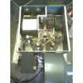
There is no reason you cant share a power wire that feeds the amp with the radio. I have a large power wire running from the battery through a firewall grommet to a junction block behind my seat. I can run many different pieces of equipment from this junction block. Just fuse everything seperate. I will include pics that show a universal grounding point that I have placed nearby. It is connected straight to the frame by a grounding strap.
The firewall grommet. Used for safe passage of wire through firewall.
[ external image ]
Junction block for distribution of power
[ external image ]
Star ground (note only the amp is hooked to it but, a wingnut allows attachment of any other grounds.
[ external image ]
hope this helps Gummybear
S/F
GUNNY
-
Gummybear
- Skipshooter
- Posts: 349
- Joined: January 17th, 2009, 8:43 pm
- Real Name: Samual
- Radio: 2-way baby monitor
- Contact:
-
Foxhunter
- Donor
- Posts: 2,651
- Joined: April 3rd, 2008, 11:24 am
- Radio: Fisher-Price
- Contact:
'Doc wrote:backwoods,
About the electrical and RF grounding thing. Take a look at the NEC National Electrical Code. Your library may have a copy. It deals with both electrical and radio grounding among other things.
- 'Doc
Just was looking over the thread and thought to post a comment on the NEC reference above, it's a good source and I have the book (somewhere) on my reference shelves. Also wanted to say that many if not most of the grounding principles are the same for fixed and mobile stations alike for the most part, the fundamentals are the same. The NEC reference mentioned above is for the National Electrical Code NEC Section 800, completely aligned with the ARRL, REACT and other radio organizations.
NEC Section 800
"Radio and Television Equipment [Article 810]. The antenna mast that supports radio, HAM, television and satellite receiving antennas must be grounded [810.15]. In addition, each conductor (coaxial, control, and signal conductors) of a lead-in from an "outdoor antenna" must be provided with a listed antenna discharge unit (grounding block). The antenna discharge unit shall be grounded and it must be located outside or inside as near as practicable to the entrance of the conductors to the building and it must not be located near combustible material [810.20].
The grounding conductor for the mast and discharge unit shall not be smaller than 10 copper AWG and it’s length shall be as short as practicable run in as straight a line as practicable [800.21].
Grounding of the antenna mast and lead-in cables in accordance with the NEC is somewhat effective in protecting receiving equipment from voltage surges, as well as voltage transients from lightning. If the mast is not properly grounded, the Low Noise Block (LNB), as well as the dc rotor motors that control the positioning larger satellite dishes often will be destroyed by voltage surges caused by nearby lightning strikes. If the lead-in from an outdoor antenna is not properly earth grounded in accordance with the NEC, the receiver can be destroyed by voltage surges caused by nearby lightning strikes."
*********
I'd keep the above in-mind when doing a base installation. The quote above is only a small introductory excerpt of the complete section, which is much larger with specific instructions. But seriously, I consider doing this not only for best installation results and safety---but also for HOMEOWNERS/FIRE INSURANCE REASONS. If by some chance, you were to be unfortunate enough to have a house fire, due to an equipment fault or perhaps even a lightning strike or some other reason----if your radio system installation was not properly installed to code----you might be found "at fault" for a do-it-yourself improper installation, a non-professional not-to-code install done by "the homeowner". Insurance companies are always looking to avoid paying a claim. Who better to blame than you ?
*********
NEC Article 250.4. This details the general requirements for grounding and bonding. It begins by distinguishing between, and giving requirements for, five categories of grounding: Electrical system grounding, Grounding of electrical equipment, Bonding of electrical equipment, Bonding of electrically conductive materials and other equipment, and Effective ground-fault current path. It also identifies and gives requirements for four categories of ungrounded systems. Figure 250.4 is a great visual for seeing which Parts of NEC Article 250 apply to various aspects of grounding.
NEC Article 250.6 addresses another fundamental concept of grounding. That is, the prevention of "objectionable current flow over the grounding conductors or grounding paths."
NEC Article 250.52 gives the requirements for grounding electrodes. This is a more complex topic than most people think. IEEE-142 gives a thorough theoretical treatise of it. The NEC just gives the minimal requirements for safety.
NEC Article 250.58 instructs us to use "the same electrode for grounding conductor enclosures and equipment in or on that same building." The concept of "separate ground" is nonsense. Two good sources for more information on this are Soares Book on Grounding and IEEE-142.
[Please login or register to view this link]
Now here's a decent one-page Wikipedia article (with useful links) on Ground Loops:
Wikipedia Ground Loops
[Please login or register to view this link]
Foxhunter 351 NJ


![[ external image ]](http://www.radioworks.com/nbgnd2.jpg)
![[ external image ]](http://www.radioworks.com/nbgnd5.jpg)
![[ external image ]](http://i402.photobucket.com/albums/pp108/foxhunter351/Radio%20Diagrams%20ETC/GroundLoop3.gif)
![[ external image ]](http://i402.photobucket.com/albums/pp108/foxhunter351/Radio%20Diagrams%20ETC/GroundLoop4.gif)
![[ external image ]](http://i402.photobucket.com/albums/pp108/foxhunter351/Radio%20Diagrams%20ETC/GroundLoop5.gif)
![[ external image ]](http://i402.photobucket.com/albums/pp108/foxhunter351/Radio%20Diagrams%20ETC/nbgnd2.jpg)
![[ external image ]](http://i402.photobucket.com/albums/pp108/foxhunter351/Radio%20Diagrams%20ETC/nbgnd5.jpg)
![[ external image ]](http://i439.photobucket.com/albums/qq112/zimmermannnk/firewallgrommet.jpg)
![[ external image ]](http://i439.photobucket.com/albums/qq112/zimmermannnk/insideofjunctionblock.jpg)
![[ external image ]](http://i439.photobucket.com/albums/qq112/zimmermannnk/junctionblockandampinstall.jpg)